The Kirra Blasting App is a gift to the blasting community, a legacy.
The application stands as homage to enduring methods, offering a no-cost, educational platform for those without access to costly, mainstream mining applications. Crafted with passion, its simplicity ensures usability even for communities with less access to facilities.
While free, the support might not always be immediate due to the developer's solo efforts.
Contributions to support the developer's ongoing enhancements in features, stability, and functionality are welcomed via the "Buy Me a Coffee" platform. Your generosity can propel the app's evolution and sustain its
community-driven spirit.
Getting Started
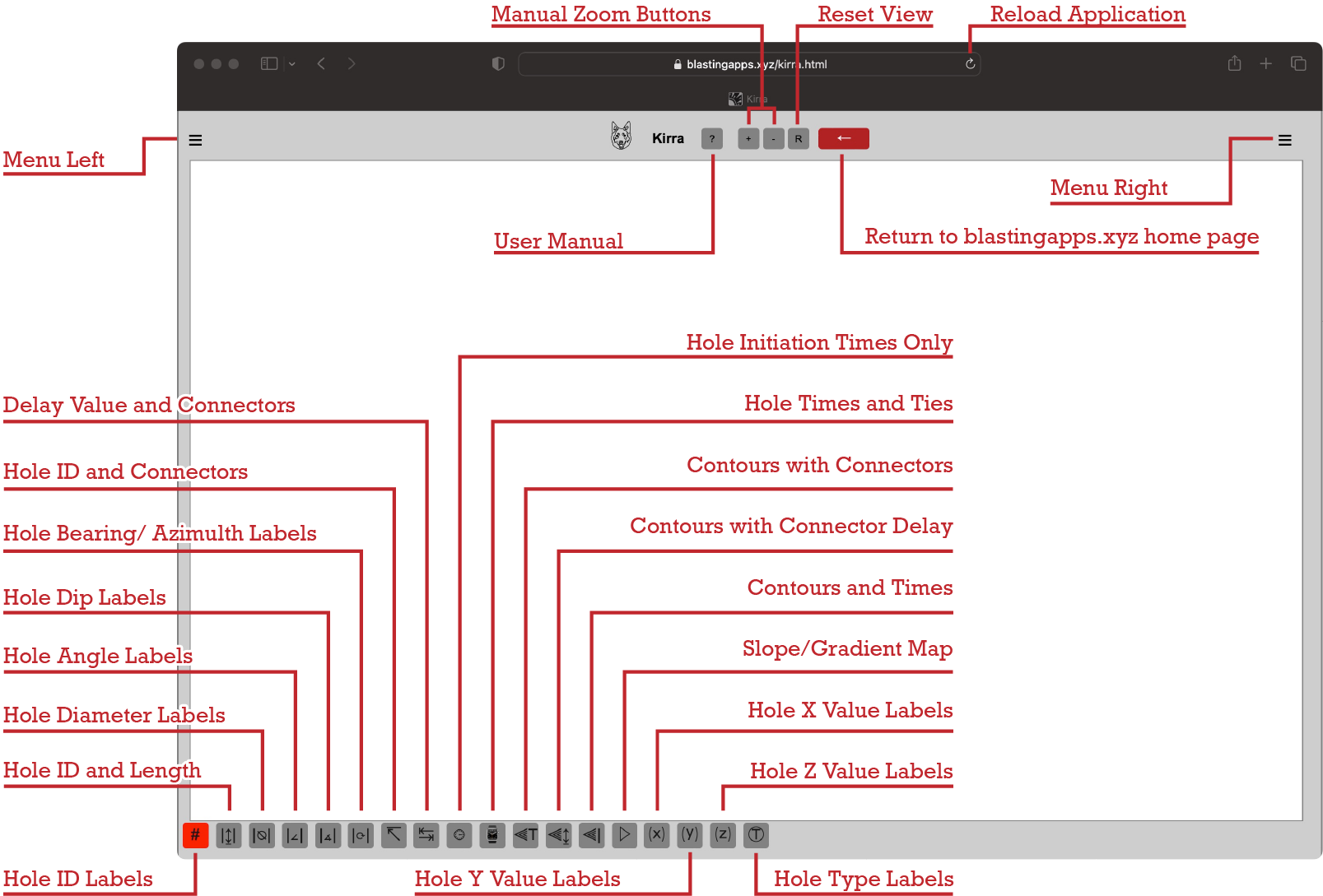
User interface
Quick Start Guide:
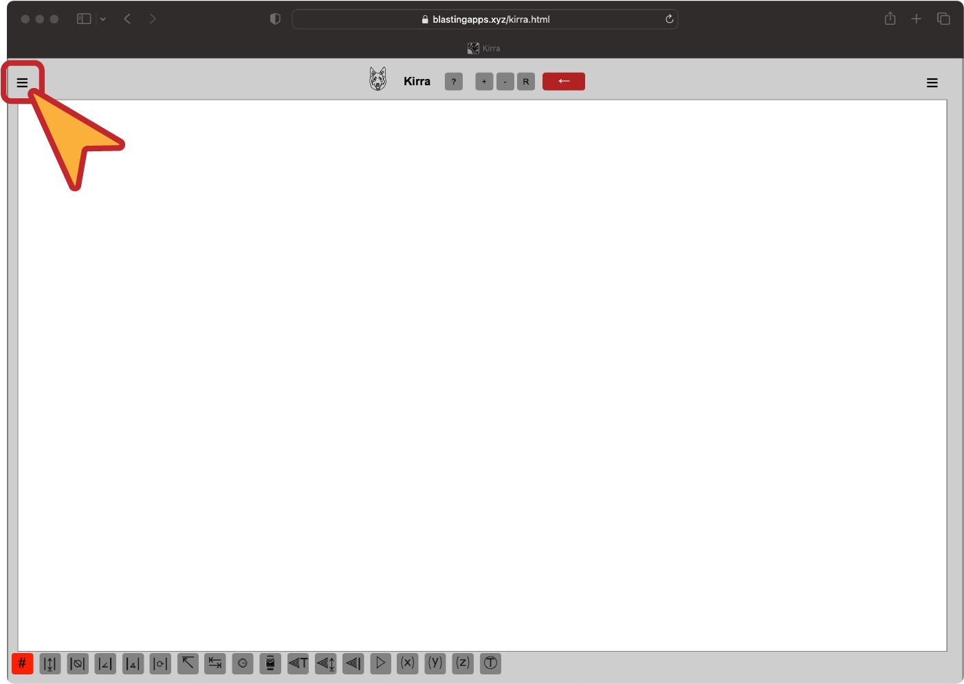
Open the application
Click on the "Menu Left" button
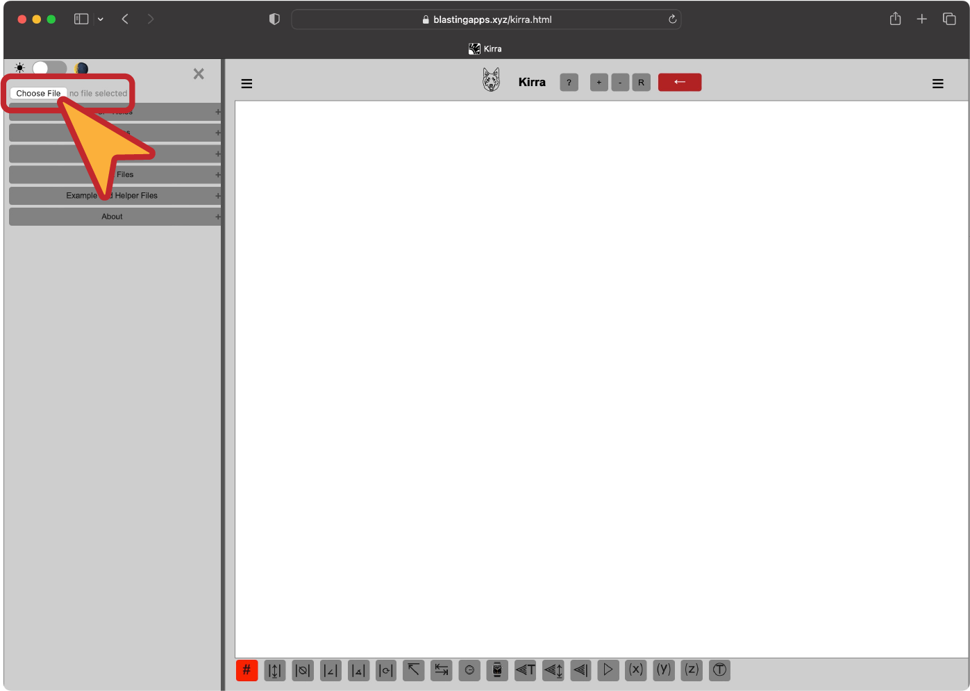
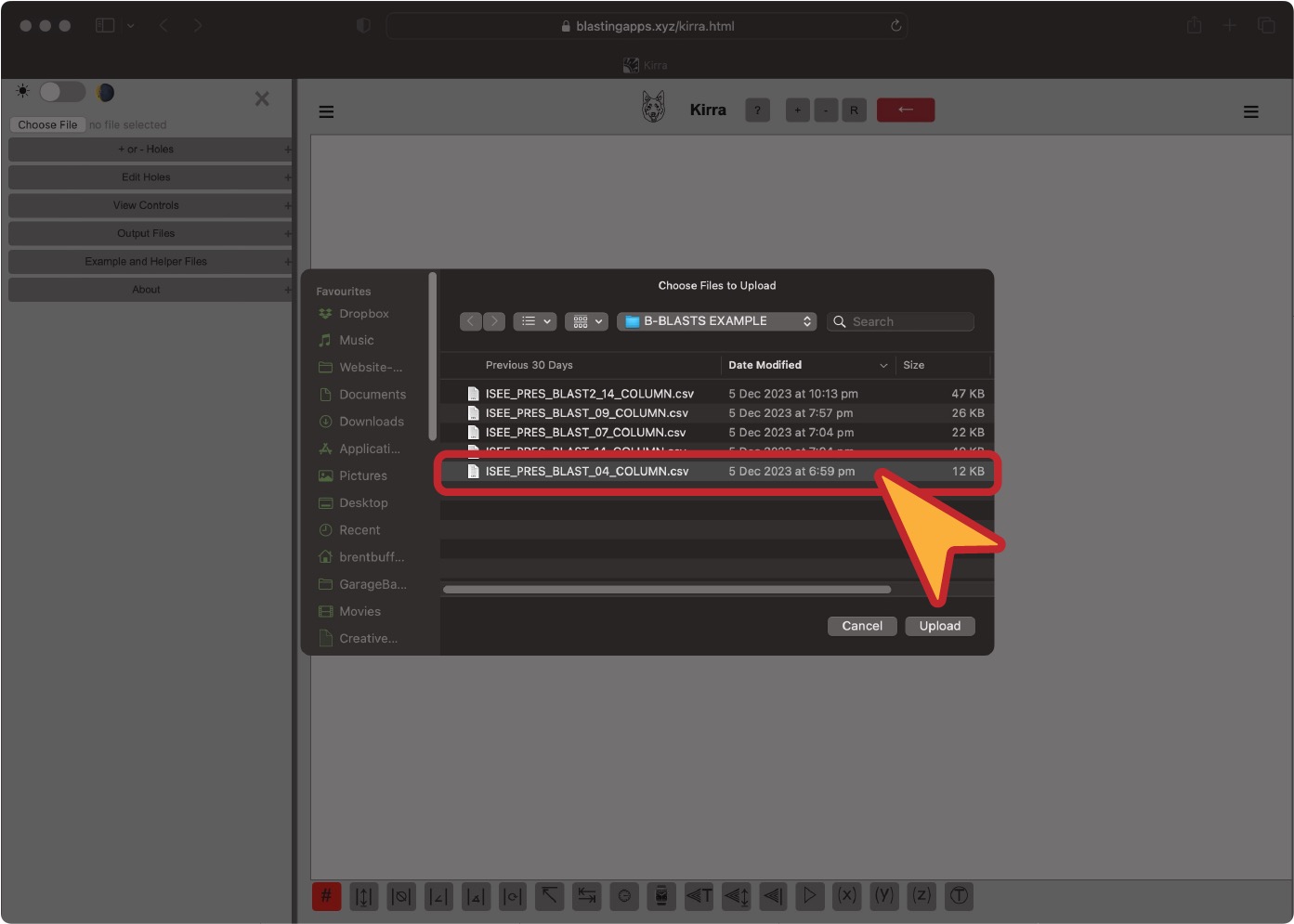
Choose a file to open with the "Choose File" button
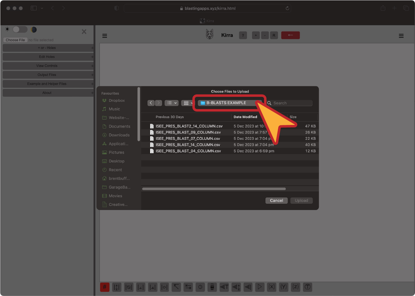
Navigate to the file
Click on the file you want to import
File needs to be one of the supported formats
4 column csv file
7 column csv file
9 column csv file
12 column csv file
14 column csv file
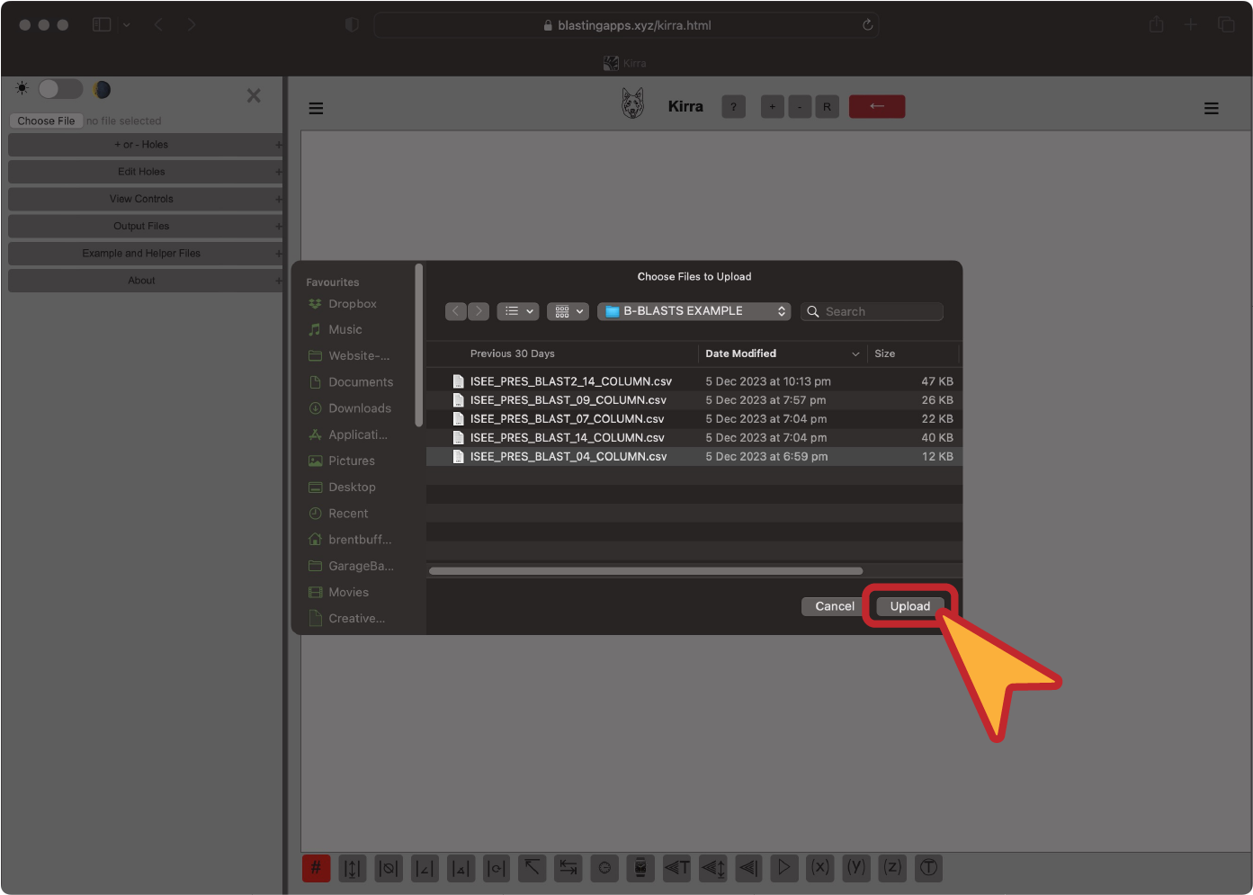
Click on the "Upload" button
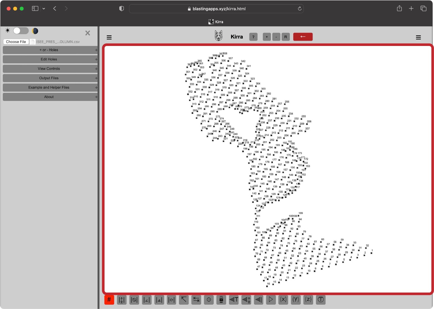
View file in the application
Click on the "Menu Left" button
Choose a file to open with the "Choose File" button
Navigate to the file
Click on the file you want to import
Click on the "Upload" button
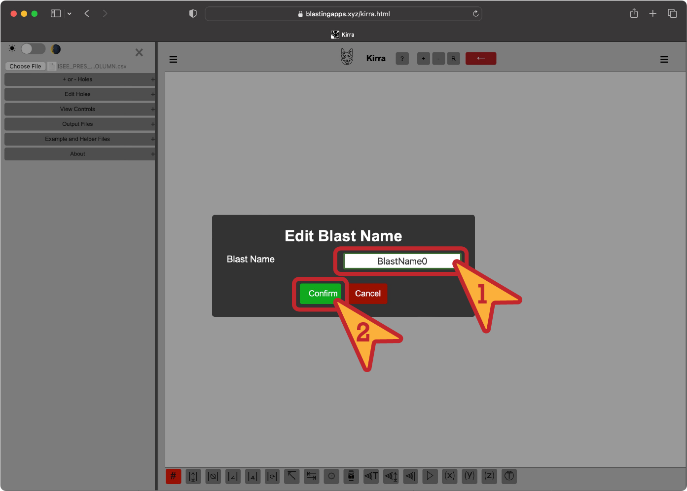
Enter a blast name (except on 14 column csv files)
View file in the application
Below is the quide in GIF format:
Loading a file:
Creating a blast:
Features
Supported file types:
Current Kirra Blasting App supports several file types and structures. Kirra can accept what are known as human readable "flat files".
These types of files are used commonly in the blasting industry to transport a multitude of different sets of data from one program to another.
Almost all programs used in mining can accept files that have values separated by commas or tabs. The files that Kirra uses are the similar.
As are the files that Kirra can export.
However the files must consist of a fixed structure depending on their purpose. The drawing files are fixed and may be confusing to generate manually.
The holes files are also fixed to various column numbers and the data must be in the correct columns. The data must also be in the correct format.
The best results come from ensuring the file is formatted correctly.
Files types supported by Kirra are as follows:
Text files (.txt) - These are still comma separated value files however they use the .txt suffix to denote drawing.
These files are used to store drawing data in a human readable format.
The files are still comma separated value files however they use the .txt suffix to denote drawing.
They can be opened in any text editor and can be edited manually.
They can also be opened in Excel and other spreadsheet programs.
Comma Separate Values (.csv) - These are comma separated value files.
These files are used to store hole and point data in a human readable format.
They can be opened in any text editor and can be edited manually.
They can also be opened in Excel and other spreadsheet programs.
Kirra Drawing (.kad) - These are comma separated value files however they use the .kad suffix
These .kad files are ONLY usable in the desktop application.
They files are used to store drawing data in a human readable format.
They can be opened in any text editor and can be edited manually.
Use the .txt format for drawing files if you wish to use the application on iPad or iPhone.
File Structure:
Example [points] drawing entity (do not include the header line):
entityName
entityType
pointID
pointXLocation
pointYLocation
pointZLocation
colour
POINTNAME
point
1
12345.678
98765.432
789.987
red
Example [line] drawing entity (do not include the header line):
entityName
entityType
pointID
pointXLocation
pointYLocation
pointZLocation
lineWidth
colour
LINENAME1
line
1
12345.678
98765.432
789.987
1
red
LINENAME1
line
2
12346.678
98763.432
789.987
1
red
LINENAME2
line
1
12345.678
98765.432
789.987
2
blue
LINENAME2
line
2
12341.678
98768.432
789.987
2
blue
Example [poly] drawing entity (do not include the header line):
entityName
entityType
pointID
pointXLocation
pointYLocation
pointZLocation
lineWidth
colour
POLYNAME
line
1
12345.678
98765.432
789.987
1
green
POLYNAME
line
2
12346.678
98766.432
789.987
1
green
POLYNAME
line
3
12340.678
98765.432
789.987
2
green
POLYNAME
line
4
12343.678
98763.432
789.987
2
green
Example [text] drawing entity (do not include the header line):
entityName
entityType
pointID
pointXLocation
pointYLocation
pointZLocation
text
colour
TEXTNAME
text
1
12345.678
98765.432
789.987
Calculatable
red
Example [circle] drawing entity (do not include the header line):
entityName
entityType
pointID
pointXLocation
pointYLocation
pointZLocation
radius
lineWidth
colour
CIRCLENAME
circle
1
12345.678
98765.432
789.987
10
1
red
Example [4 column CSV] holes file (header line optional):
holeID
startXLocation
startYLocation
startZLocation
1
12340.000
98765.432
789.987
2
12343.500
98765.432
789.987
3
12347.000
98765.432
789.987
Example [7 column CSV] holes file (header line optional):
holeID
startXLocation
startYLocation
startZLocation
endXLocation
endYLocation
endZLocation
1
12340.000
98765.432
789.987
12340.000
98765.432
779.987
2
12343.500
98765.432
789.987
12343.500
98765.432
779.987
3
12347.000
98765.432
789.987
12347.000
98765.432
779.987
Example [9 column CSV] holes file (do not include the header line):
holeID
startXLocation
startYLocation
startZLocation
endXLocation
endYLocation
endZLocation
diameter
holeType
1
12340.000
98765.432
789.987
12340.000
98765.432
779.987
140
Batter
2
12343.500
98765.432
789.987
12343.500
98765.432
779.987
140
Batter
3
12347.000
98765.432
789.987
12347.000
98765.432
779.987
140
Batter
Example [12 column CSV] drawing entity (do not include the header line - fromHoles that are the same as the Blast:::holeID are initiation holes
fromHoleID "BlastName:::holeID" needs to be the BlastName that you will name it):
holeID
startXLocation
startYLocation
startZLocation
endXLocation
endYLocation
endZLocation
diameter
holeType
fromHole
delay
colour
1
12340.000
98765.432
789.987
12340.000
98765.432
779.987
140
Batter
Blast1:::1
25
red
2
12343.500
98765.432
789.987
12343.500
98765.432
779.987
140
Batter
Blast1:::1
25
red
3
12347.000
98765.432
789.987
12347.000
98765.432
779.987
140
Batter
Blast1:::2
25
red
PREFERRED FORMAT
Example [14 column CSV] holes file (do not include the header line - fromHoles that are the same as the Blast:::holeID are initiation holes
fromHoleID "BlastName:::holeID" needs to be the BlastName that you will name it):
entityName
entityType
holeID
startXLocation
startYLocation
startZLocation
endXLocation
endYLocation
endZLocation
diameter
holeType
fromHole
delay
colour
Blast1
hole
1
12340.000
98765.432
789.987
12340.000
98765.432
779.987
140
Batter
Blast1:::1
25
red
Blast1
hole
2
12343.500
98765.432
789.987
12343.500
98765.432
779.987
140
Batter
Blast1:::1
25
red
Blast1
hole
3
12347.000
98765.432
789.987
12347.000
98765.432
779.987
140
Batter
Blast1:::2
25
red
Left Menu ☰
Contents:
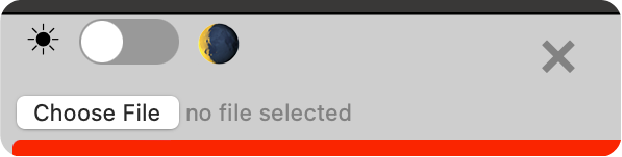
Light and Dark Mode
Choose a mode to work in, either dark or light. The default is light mode. The mode resets if you have to clear the browser cache. The mode stays persistent once selected until the cache is cleared.
Choose File
Click the "Choose File" button to open a file browser and select a file that is compatible with Kirra (refer to File structure).
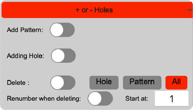
Click the + or - buttons expand the custom blast creation and deletion functions.
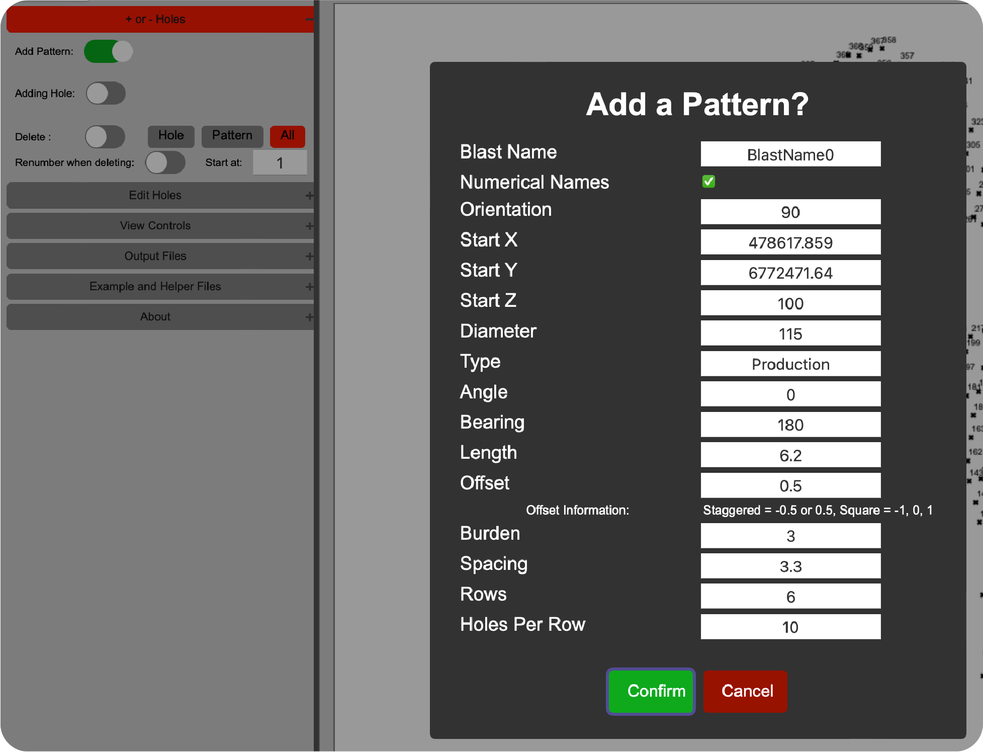
Add Pattern Click the switch adjacent to the text "Add Pattern". You are now in the pattern add mode. Next click on the canvas to bring up the pattern add dialog options. Enter the values that you want to and click confirm.
Important! the blast
must have a name or other functions may not work. A blast name also denotes that the holes created belong to the named blast. The program attempts to provide a name for you however you may choose any names for the blast you like. Generally minessites use a
naming convention of Pit, cutback or push, reduced/relative level and a blast
sequence
number. e.g. "NW3-200-001"
Numerical Names are also supported. e.g. "1", "2", "3" etc. by default. The option to use Alpha-numerical names is available by unchecking the "Numerical Names" checkbox.
Offset is the value that results in a Staggered or Square pattern. Values of 0.5 or 1.5 are common for staggered patterns. Values of 0 or 1 are common for square patterns.
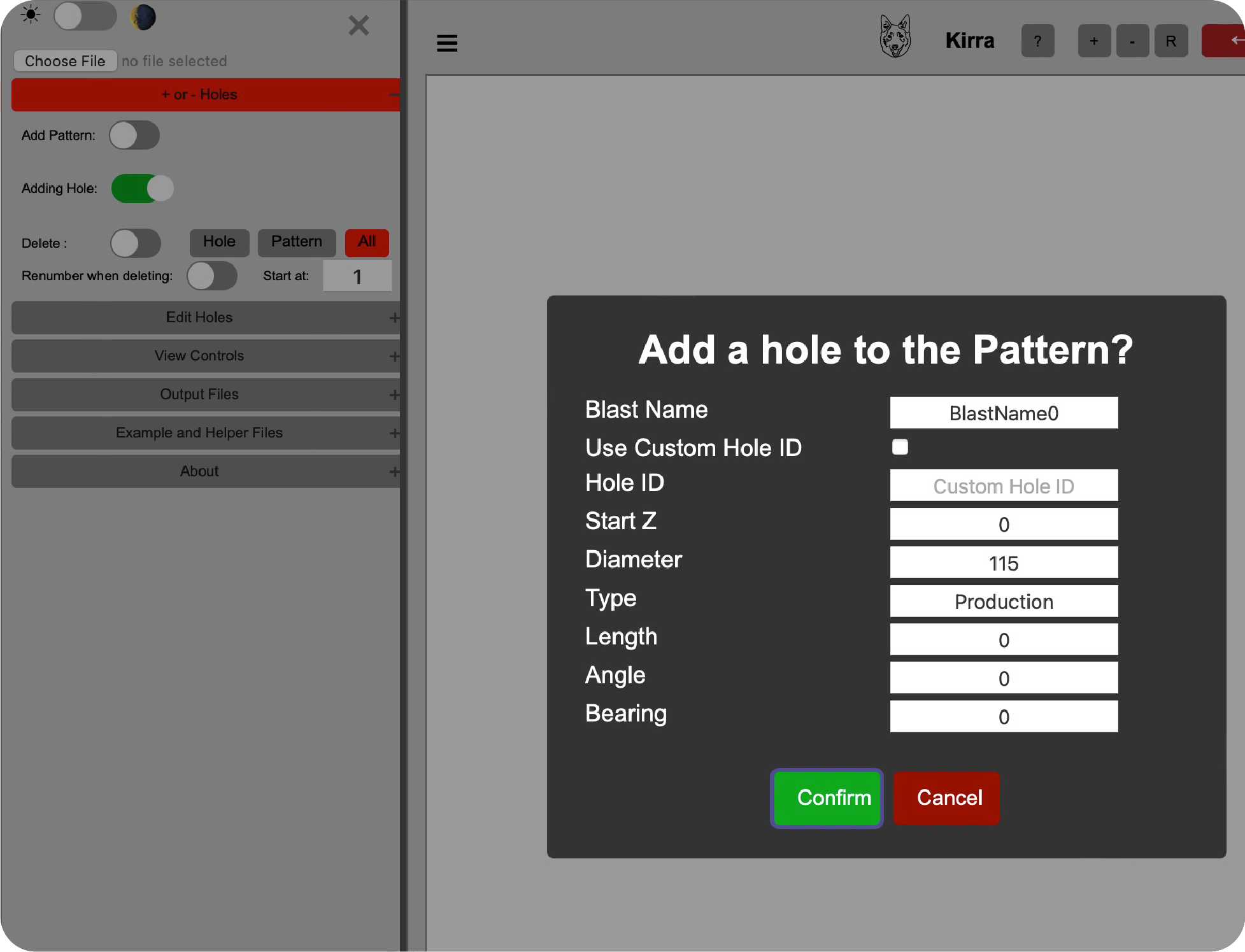
Add Hole Click the switch adjacent to the text "Add Hole". You are now in the add hole mode. Next click on the canvas to bring up the pattern add dialog options. Enter the values that you want to and click confirm.
Important! the blast must have a name or other functions may not work.
When adding a hole the name of the blast needs to be considered. If you add a hole to a unrelated blast it is now related to that blast.
If you want to alter it due to a mistake then you must use:
[Edit Hole] → [Edit Blast Name] (with the apply to all holes in blast unchecked).
The program attempts to provide a name for you however you may choose any names for the blast you like. Generally mines sites use a naming convention of Pit, cutback or push, reduced/relative
level and a blast sequence number. e.g. "NW3-200-001"
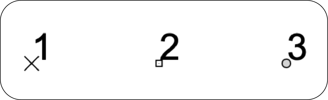
Creating a blast hole without a diameter or length will result in a cross shaped hole.(commonly known as a Dummy Hole)
Creating a blast hole with out diameter however with a length will result in a box shaped hole.
Creating a blast hole with a diameter and length will result in a circluar shaped hole.
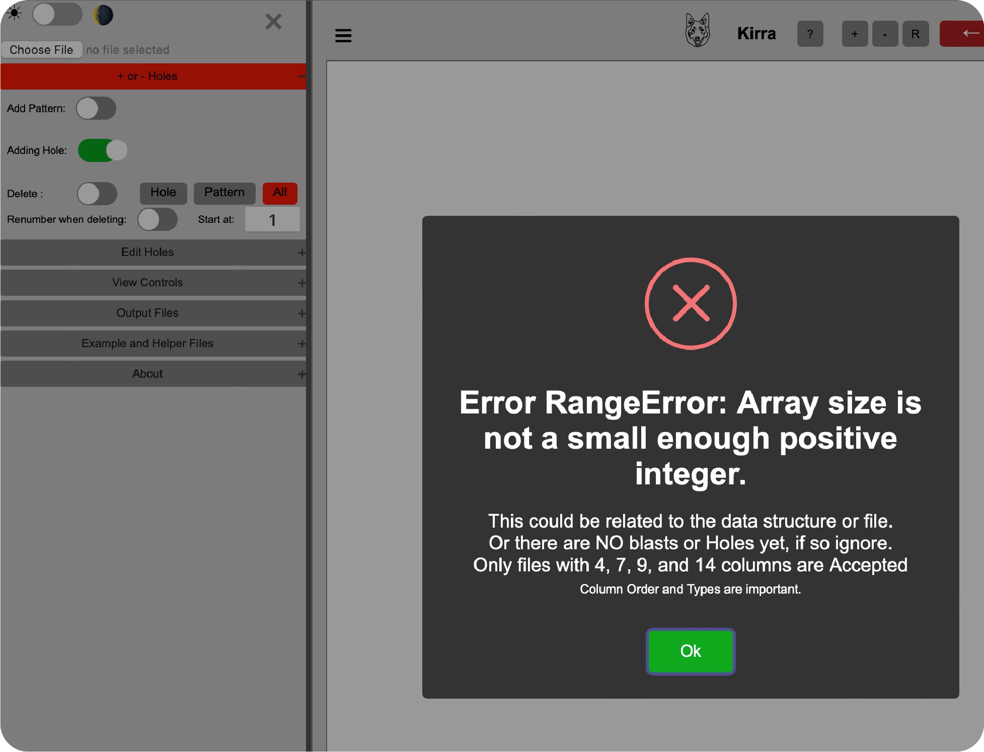
Important! If you receive an Error message like the one below then you do not have any holes in the hole information yet, If you do have holes Reload the browser as the data may be corrupted and need a refresh.
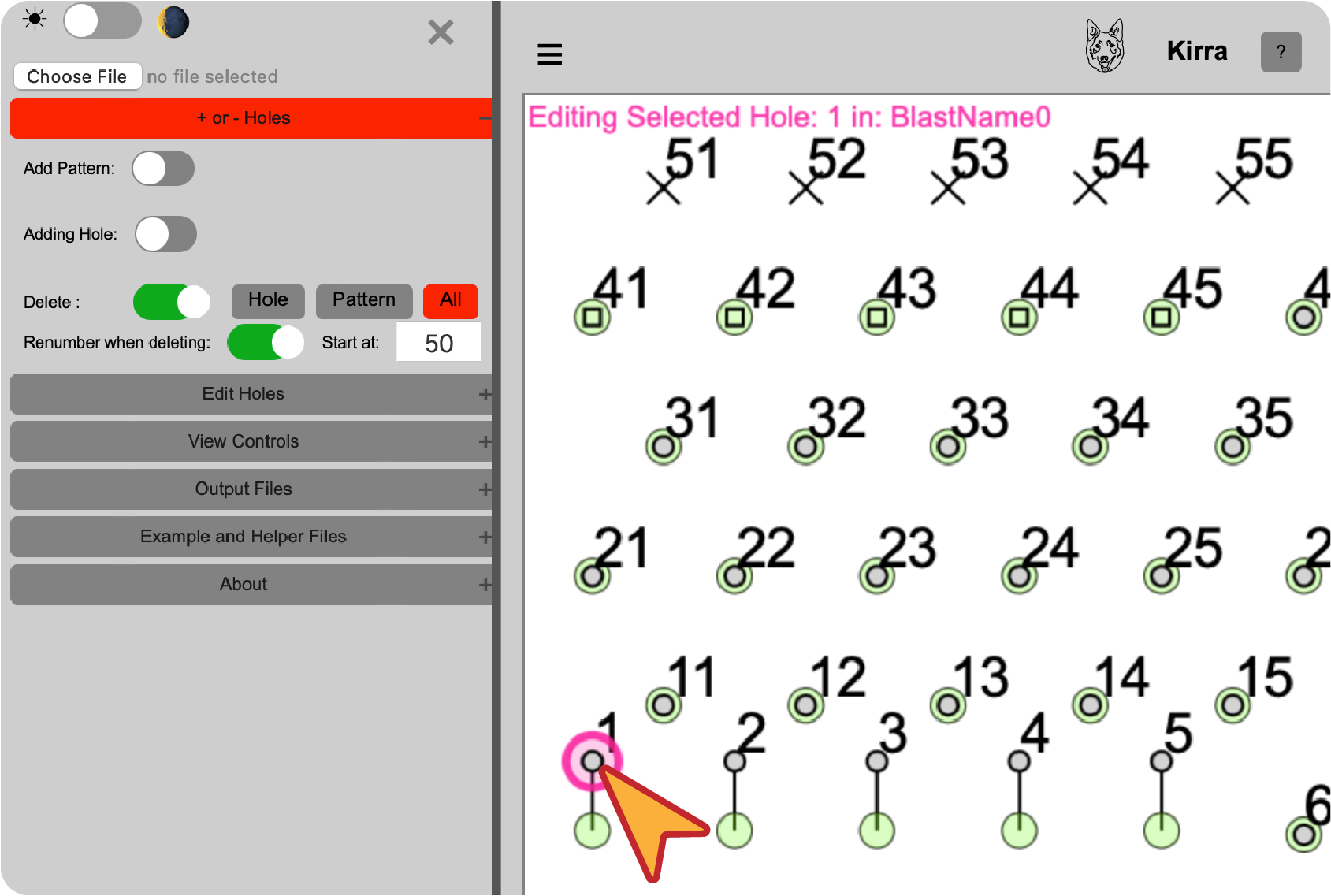
Delete Hole, Pattern or All Patterns Click the switch adjacent to the text "Delete". You are now in the delete hole mode. Next click on a hole in the canvas.
This will select the holes. A selected hole will have a highlight around it. Next click the mode of deletion you want to use. (Hole, Pattern or All).
Hole removes the selected hole from that blast.
Pattern removes the selected pattern from the blast. If two or more blasts are present they will not be affected.
There is one condition to this, if the blast name is the same as another blast then the application considers them to be the same blast and if they do not have unique names both patterns will be deleted.
All removes all patterns from the data model.
Renumber when deleting The holes after the selected hole has been deleted will be re-numbered sequentially from the [Start At] value incrementally to the last hole (this is only avalable for Numerical Hole ID Values).
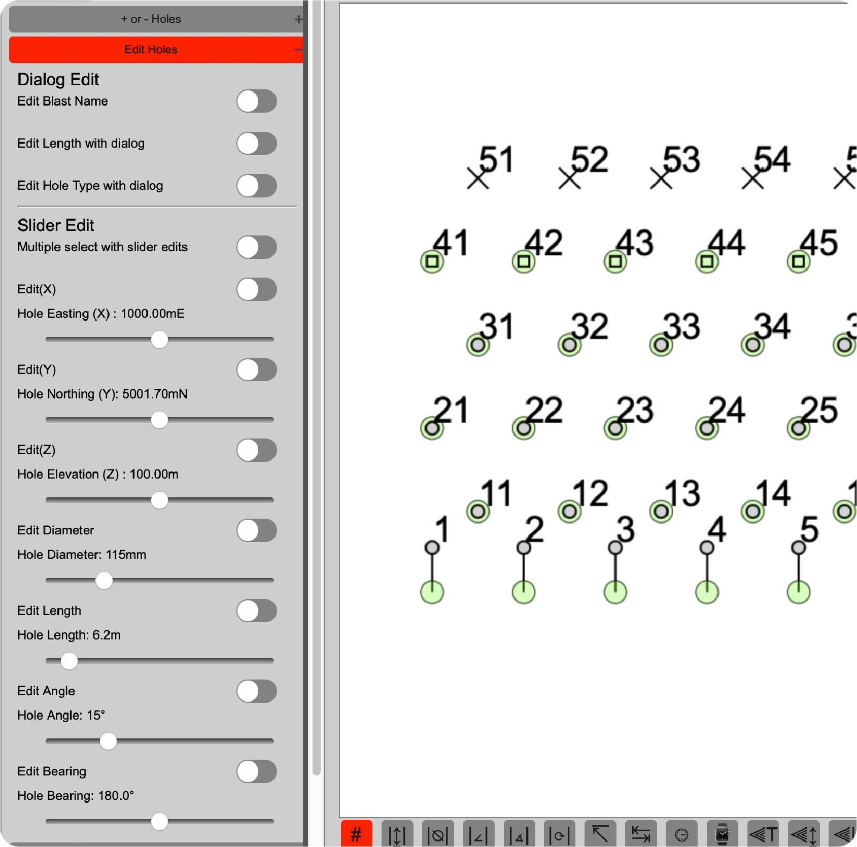
Edit Holes contains many functions to modify the location and attributes of the blast hole in the design. There are two sections, a "Dialog Edit" section and a "Slider Edit" section.
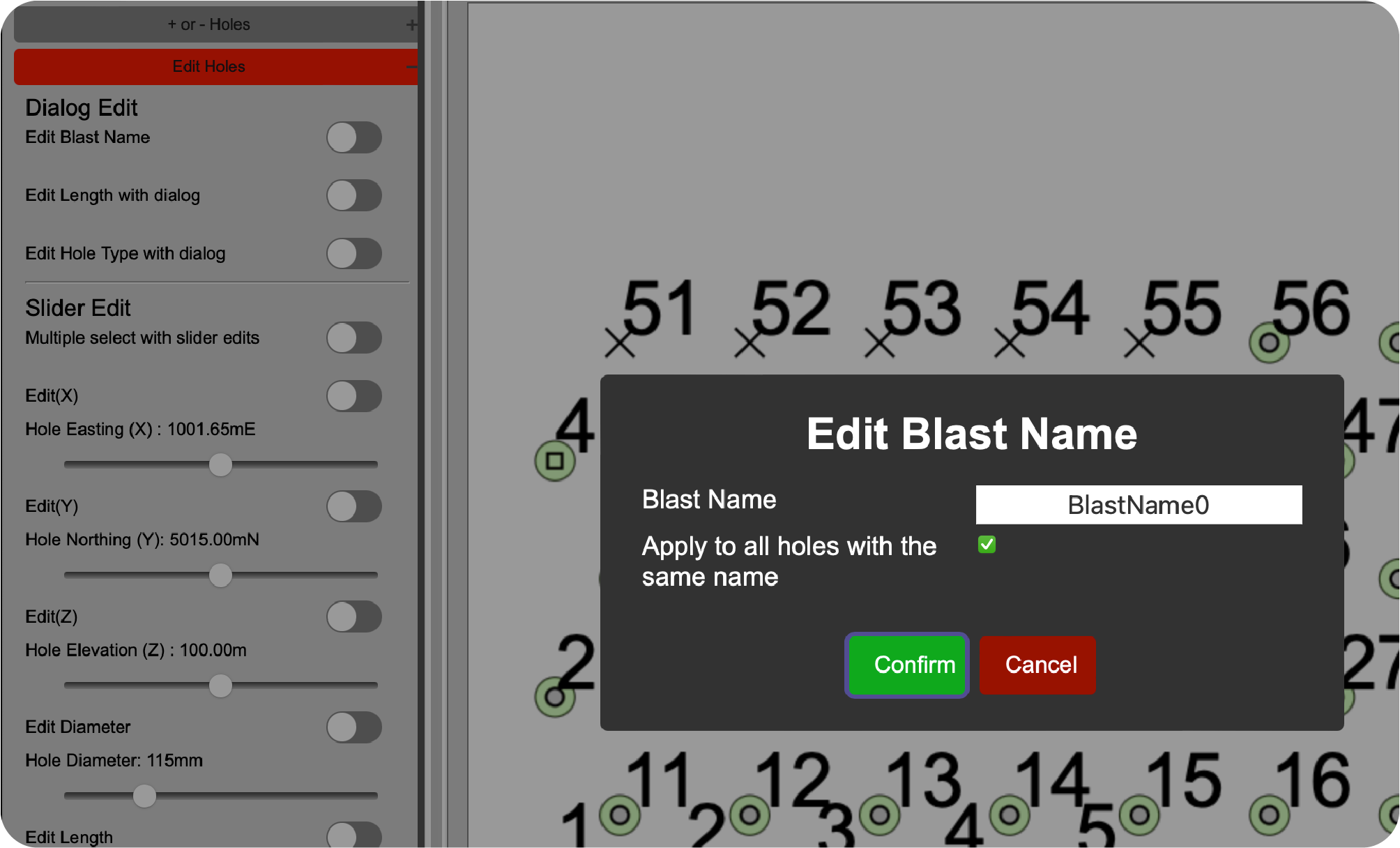
The "Dialog Edit" section contains the following functions: Edit Blast Name click the switch adjacent to the text "Edit Blast Name". Next click on a hole in the canvas.
To move the hole to another blast apply the blast name change to only the one hole by unchecking the "Apply to all holes with the same name".
In order to change the entire blasts name or to join to blasts leave the "Apply to all holes with the same name" checked. This will adjust all blast hole's blast name.
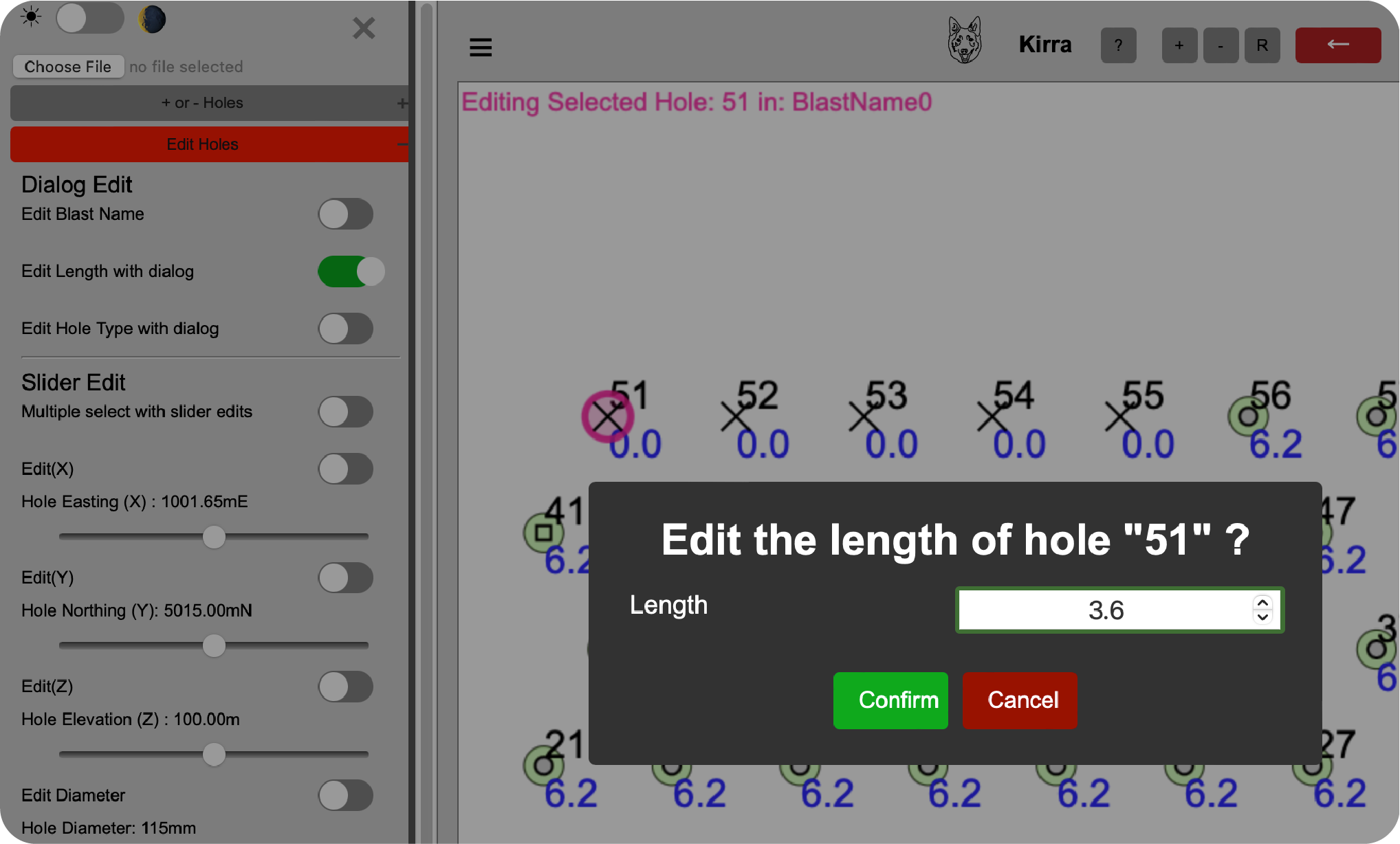
Edit Length with Dialog click the switch adjacent to the text "Edit Length with Dialog". Next click on a hole in the canvas. This is a single selection function ONLY currently and will only work on one hole at a time.
This will open the edit length dialog, enter the new length value. This is especially useful for measuring blast holes in field.
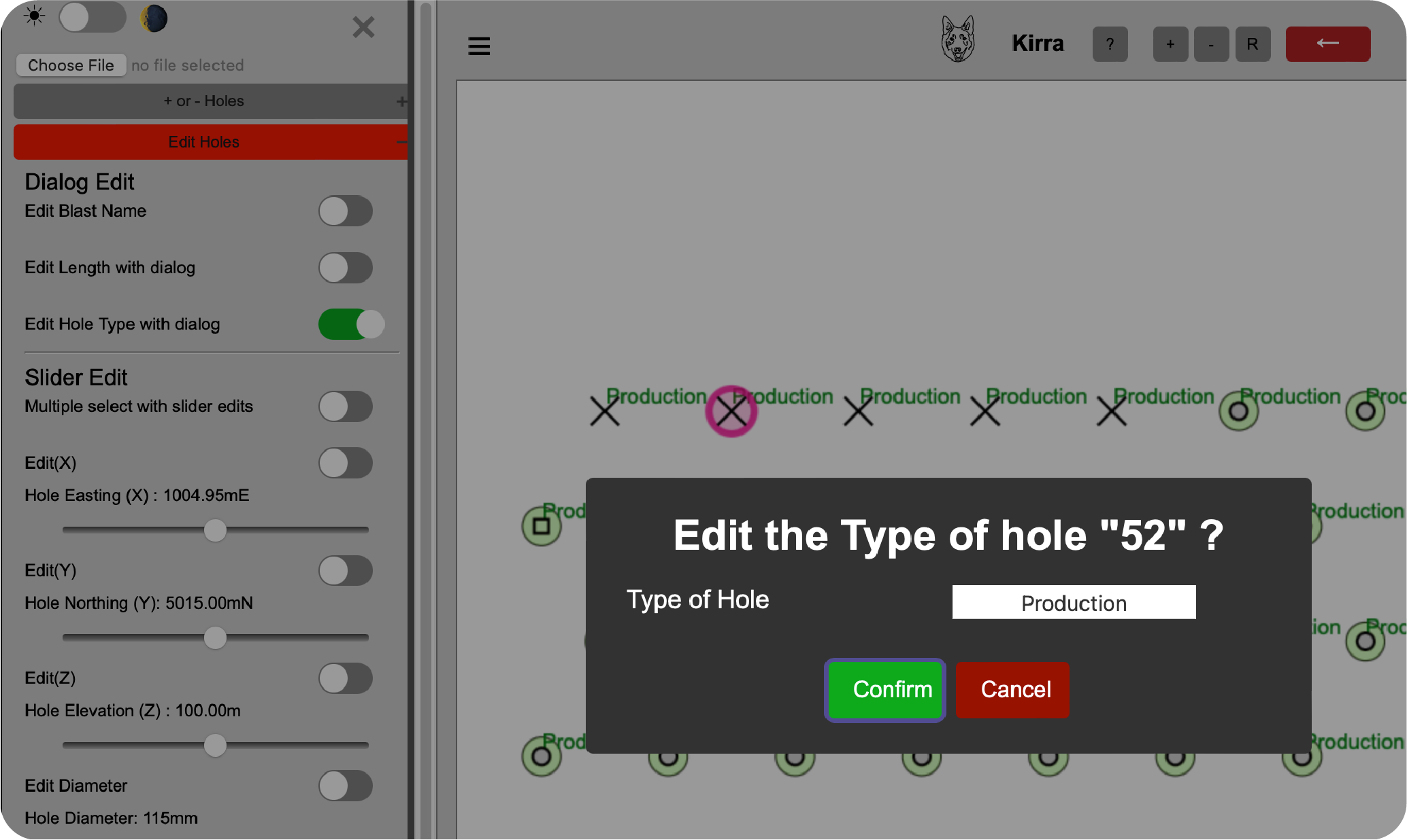
Edit Hole Type with Dialog click the switch adjacent to the text "Edit Hole Type with Dialog". Next click on a hole in the canvas. This is a single selection function ONLY currently and will only work on one hole at a time.
This will open the edit type dialog, enter the new value.
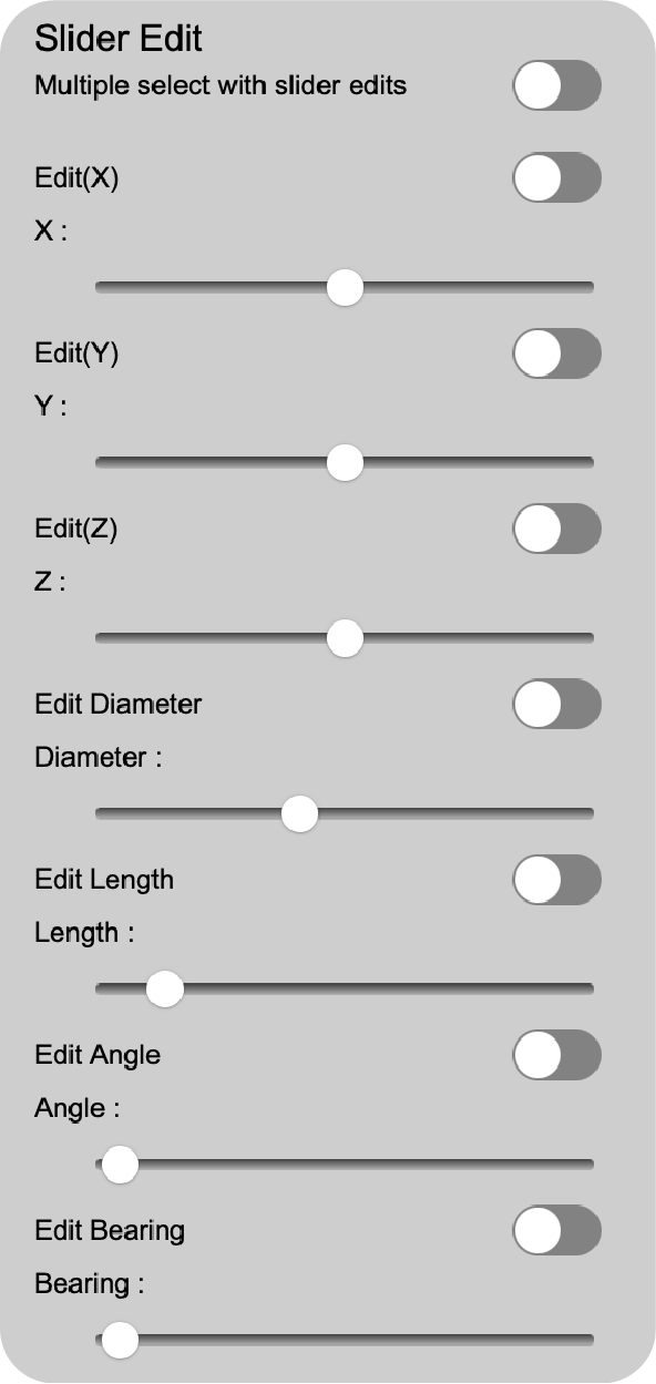
The "Slider Edit" section contains the following functions:
Multiple select with slider edits click the switch adjacent to the text "Multiple select with slider edits". This is a multiple selection function and will when using the slider editors.
You need to have one of the other selection "slider edit" mode engaged when using the multiple select mode. Select the holes you want to edit by clicking on them. A selected hole will have a highlight around it.
If you do not have the "Multiple select with slider edits" switch engaged then the selection will be cleared when you select another hole. This is single selection mode.
Edit(X) click the switch adjacent to the text "Edit(X). Next click on a hole in the canvas. Then move the slider to the desired value.
You only get 20 meters of movement in either direction of a hole's original value at a time. This is to stop you from accidentally moving a hole too far.
In order to move the hole an additional 20 meters you must unselect the hole by turning off the "Edit(X)"" mode and then turning on the "Edit(X) mode and reselecting the hole and moving it.
Edit(Y) click the switch adjacent to the text "Edit(Y). Next click on a hole in the canvas. Then move the slider to the desired value.
You only get 20 meters of movement in either direction of a hole's original value at a time. This is to stop you from accidentally moving a hole too far.
In order to move the hole an additional 20 meters you must unselect the hole by turning off the "Edit(Y)"" mode and then turning on the "Edit(Y) mode and reselecting the hole and moving it.
Edit(Z) click the switch adjacent to the text "Edit(Z). Next click on a hole in the canvas. Then move the slider to the desired value.
You only get 20 meters of movement in either direction of a hole's original value at a time. This is to stop you from accidentally moving a hole too far.
In order to move the hole an additional 20 meters you must unselect the hole by turning off the "Edit(Z)"" mode and then turning on the "Edit(Z) mode and reselecting the hole and moving it.
Edit Diameter click the switch adjacent to the text "Edit Diameter". Next click on a hole in the canvas. Then move the slider to the desired value.
The slider is set to 0 to 500 millimeters. This is to stop you from creating implausible blast holes.
Edit Length click the switch adjacent to the text "Edit Length". Next click on a hole in the canvas. Then move the slider to the desired value.
The slider is set to 0 to 100 meters. This is to stop you from creating implausible blast hole lengths.
To create holes longer than this amount use the "Edit Length with Dialog" function.
Edit Angle click the switch adjacent to the text "Edit Angle". Next click on a hole in the canvas. Then move the slider to the desired value.
The slider is set to 0 to 60 degrees. This is to stop you from creating implausible blast hole angles.
Edit Bearing click the switch adjacent to the text "Edit Bearing". Next click on a hole in the canvas. Then move the slider to the desired value.
The slider is set to 0 to 360 degrees. This is to stop you from creating implausible blast hole bearings.
You can have all the "Edit(X)", "Edit(Y)", "Edit(Z)", "Edit Diameter", "Edit Length", "Edit Angle" and "Edit Bearing" switches engaged at the same time.
Turning one of the modes off will clear all the selections. You will have to reselect the hole(s) you want to edit.
Record Length with dialog click the switch adjacent to the text "Record Length with dialog". Next click on a hole in the canvas. Then record the desired value.
The timestamp will be attached to the record and the hole will be updated with a recorded length. The Design Length will not be altered.
Record Mass with dialog click the switch adjacent to the text "Record Mass with dialog". Next click on a hole in the canvas. Then record the desired value.
The timestamp will be attached to the record and the hole will be updated with a recorded mass.
Record Comment with dialog click the switch adjacent to the text "Record Comment with dialog". Next click on a hole in the canvas. Then record the desired comment.
The timestamp will be attached to the record and the hole will be updated with a recorded mass.
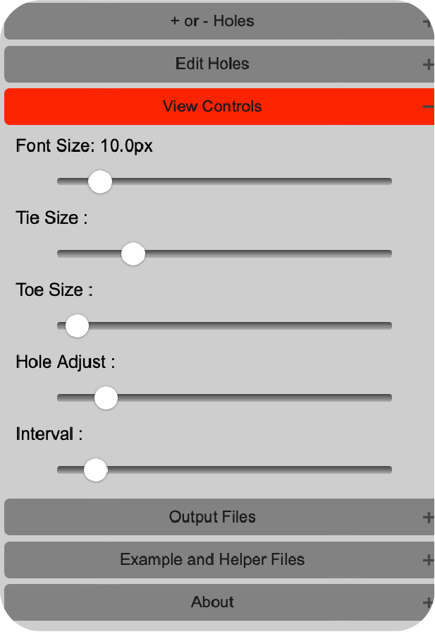
View Controls contains many functions to modify the view of the blast design in the canvas.
Font Size controls the display of the fonts on the screen in pixels. It is a scaled when you zoom in and out.
Tie Size controls the display of the tie lines on the screen in pixels. It is a scaled when you zoom in and out.
Toe Size controls the display of the toe lines on the screen in meters. It is a scaled when you zoom in and out.
The "Toe Size" slider is useful for displaying the crowding and placement of the blast holes.
It can also be used in the design process to ensure that the blast holes are not too close to the toe of the bench/highwall.
Hole Adjust controls the display of the hole adjust lines on the screen in ratio. A setting of 1.0 is the real world size of the blast hole. 2.0 is twice the size of the blast hole. 1 is smallest setting.
Interval controls the display of the interval lines on the screen in milliseconds. The smallest setting is 25ms spacing. The largest setting is 1000ms spacing. The default is 100ms spacing.
Interval lines are useful for determining when blast holes are timed out of sequence.
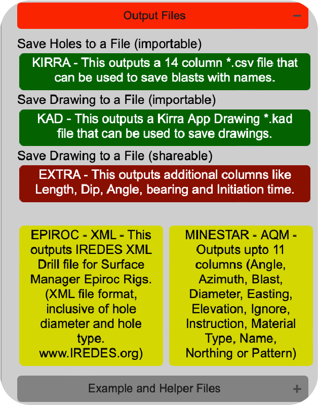
Output Files
is the save area of the application. The option presented here allow you to save your progress and also export files that other systems may use. The buttons are clearly labled as to their function.
The "KIRRA - This outputs a 14 column *.csv file that can be used to save blasts with names." button will save your progress to the browser downloads.
This is useful if you want to come back to the design later. The "Save" button will save the file to your computer. It will only save blast holes.
The "KAD - This outputs a Kirra App Drawing *.kad file that can be used to save drawings." button will save your progress to the browser downloads.
This is useful if you want to come back to the design later. The "Save" button will save the file to your computer. It will only save drawings.
The "EXTRA - This outputs additional columns like Length, Dip, Angle, bearing and Initiation time." button will save your progress to the browser downloads.
This provides you with additional information about the blast holes.
The "EXTRA - This outputs actual recordings like measured depth and charge kilograms." button will output a file of HoleID and the measured length and timestamp, measured mass and timestamp and the measured comment and its timestamp.
EPIROC - XML - This outputs IREDES XML Drill file for Surface Manager Epiroc Rigs.(XML file format, inclusive of hole diameter and hole type. www.IREDES.org) button exports to an IREDES drill format.
Unfortunately this is untested and may not work. If you have any success with this please let me know.
The IREDES organisation has been uncontactable when trying to develop this function. The developer would be interested in any feedback.
MINESTAR - AQM - Outputs upto 11 columns (Angle, Azimuth, Blast, Diameter, Easting, Elevation, Ignore, Instruction, Material Type, Name, Northing or Pattern) button exports to a MineStar AQM format.
All options and files structures are accounted for. This file has not been tested and may not work. The developer would be interested in any feedback.
Example and Helper Files has links to files that assist in the use of Kirra. The files are in the same format as the files that Kirra uses.
Also a conversion file in excel is available to reformat a file from Angle or Dip, Azimuth or Bearing and length to ToeX, ToeY and ToeZ.
About
explains some aspects of the application.
Right Menu ☰
Contents:
Connectors
section is where you can alter the connection or surface ties of a blast. Currently there are two option.
Tie-in one by one This mode is a single tie-in mode. It will only allow you to tie-in one blast hole at a time.
This is useful for tying in a blast hole that is not in the correct position.
Tie-in all in a line This mode is a multiple tie-in mode. It will allow you to tie-in all blast holes in a line.
This is useful for tying in a group of blast holes that are with in the tolerance of the "Connect Distance".
The default amout is 1.0 meters. This is the distance that the blast holes can be out of alignment and still be connected.
To increase or decrease adjust the slider.
Delay amount text field is used to adjust the amount of time in milliseconds that the blast holes will be delayed by.
The default is 25 milliseconds. This value can be any valid integer, both positive and negative. There is no product supplier specific range.
Feel free to experiment with times that suit your needs and your desired blast results. However, in practicality nonel is restrictive in its range of delays.
Those being 0ms(black), 9ms(purple/green), 17ms(yellow), 25ms(red), 42ms(white), 65ms(blue), 67ms(blue), 100ms(orange), 109ms(black), 125ms(cream) and a few more higher values.
Colour button is located adjacent to the "Delay" text field. Clicking this button will open a colour picker. Select a colour to assign to the "Connector" you will be connceting with.
Connect Distance is a slider that is used to determine the distance that the blast holes can be out of alignment and still be connected. The range is 0.1 meters to 20.0 meters.
Use this is to adjust the connection tolerance on larger or titghter patterns. Generally speaking, blasts in the designs stage can be easily connected using the default value of 1.0 meters.
However if you are connecting a blast based on actual blast hole placement, you may need to adjust this value to get the desired result.
Important! there is no undo function for this at the moment. If you make a mistake just reconnect the connector you wanted.
A blast hole can only have one connector arrow, the arrow heads represent the detonator end of the connector. Yo can have many tails but ONLY one Arrow head per hole. Connecting a different hole means you overwrite the old connector.
Animate Firing
is a simple function. Use this to watch the firing sequence play. This is NOT real time, it is only an animation for determining out of sequence blast holes.
You can speed the animation up or make it slower to determing the specific hole. "PLAY" plays the animation and "STOP" stops and resets the animation. The "Slider" adjusts the speed of the playback.
Time Window
is the display of a time chart that is binned on the number of holes firing within a window of time from zero millisconds to the last value millisecond amount.
You can adjust the millisecond binning window by adjustin the slider. You can also interact with the chart and select individual or groups of binned blast holes.
The chart is interactive and will display the number of holes in the bin. Their names and the blast they belong to are displayed in the chart. Blast holes will also be highlighted in the canvas.
Drawing Tools
are a various group of functions that add annotations to your blast these are all avaiable to be exported to a file.
The drawings are seperate from the holes. Holes an drawings cannot be in the same file at this stage. There are a range of different drawing tools and whilst they are in 2D canvas space only (currently).
These tools are all capable of drawing in 3D coordinate spaces. This is facilitated by the "Elevation" input field. The elevation field assigns the Z value of the point/linepoint .etc that you are drawing.
Elevation (Z) is the input field that is used to assign the Z value of the point/linepoint .etc that you are drawing.
The value is in meters and can be any valid number, both positive and negative. There is no product supplier specific range.
Colour chooser is located below the "Elevation" input field. Clicking this button will open a colour picker.
Select a colour to assign to the "Drawing" you will be drawing with.
Point Drawing switch the tool to active, indicated by a green highlight, you are now in the drawing point mode.
This tool draws a a simple point at the X and Y coordinates that you click on in the canvas. The Z value is the elevation value that you enter in the "Elevation" input field.
Line Drawing switch the tool to active, indicated by a green highlight, you are now in the drawing line mode.
This tool draws a a simple line from the last point that you clicked on in the canvas to the next point that you click on in the canvas. The Z value is the elevation value that you enter in the "Elevation" input field.
Polygon Drawing switch the tool to active, indicated by a green highlight, you are now in the drawing polygon mode.
This tool draws a a simple polygon from the last point that you clicked on in the canvas to the next point that you click on in the canvas. The Z value is the elevation value that you enter in the "Elevation" input field.
Circle Drawing switch the tool to active, indicated by a green highlight, you are now in the drawing circle mode.
This tool draws a circle at the X, Y and Elevation with the radius indicated by the Radius(m) input field on point that you click on in the canvas.
Text Drawing switch the tool to active, indicated by a green highlight, you are now in the drawing text mode.
This tool draws a text at the X, Y and Elevation with the text indicated by the Text input field on point that you click on in the canvas.
The text tool also has an evaluation function that allows you to enter a formula that will be evaluated and the result will be displayed as the text.
It also allows you to create line breaks in the text by using the "\n" character. This is useful for creating multi-line text. You can also use any Javascript function in the formula.
For example:
If you want to calculate the mass of a blast hole's charge you can use the following formula:
Replace the "diametermm", "chargelength" and "density" with the values that you want to use. The formula will be evaluated and the result will be displayed as the text.
If you want to calculate the rock volume a blast hole will influence you can use the following formula:
=burden * spacing * benchheight
Replace the "burden", "spacing" and 'benchheight" with the values that you want to use. The formula will be evaluated and the result will be displayed as the text.
You can then use the result of the two calcualted formulas to calculate the powder factor of the blast hole:
= mass / rockvolume
Replace the "mass" with formula 1 result and the "rockvolume" with formula 2 result. The formula will be evaluated and the result will be displayed as the text.
If you want to create multi-line text you can use the following formula:
Text1\nText2\nText3
Replace the "Text1", "Text2" and "Text3" with the values that you want to use. The formula will be evaluated and the result will be displayed as the text.
To enter a complex formula try pasting the option below into the text input field, the result will be displayed as calculated text:
='The calculated mass is: ' + ((Math.PI * (229/2)**2) * 10/1000 * 1.18).toFixed(1)+'kg. The calulated rock volume is: '+(5.5 * 6.5 * 14)+ 'm3. The calculated powder factor is: '+(((Math.PI * (229/2)**2) * 10/1000 * 1.18) / (5.5 * 6.5 * 14)).toFixed(2)+'kg/m3'
Known Bug: The text field cannot handle commas at this stage "Error" may result if you use them. When raising a number to a power use the "**" operator. Not the "^" operator or the Math.pow() function.
Even a simple string like "Hello, how are you?" will cause the string to be cut off at the comma. This is a known issue and will be fixed in a future release.
In order to correct this issue the text field will require serialization and deserialization of the text field. This is a complex task and will take some time to implement. Untill then use a "-" Or "." instead of a comma.
Drawing Removal
this functions in a similar way to Delete Holes. Select the object type you want to delete by clicking on the adjacent switch.
Once it is active, indicated by a green highlight, you are now in the drawing removal mode for that entity type. That is point, line, poly, circle or text.
Next click on a drawing in the canvas. This will select the drawing. A selected drawing will have a highlight around it. Next click the mode of deletion you want to use. (Point, Object or All).
Troubleshooting
Under Construction
Support
Contact information for support.
So... you've run out of patience and you need a hand to understand how to achieve your goals in Kirra. Alternatively, something is broken and you need to inform the developer.
Well, if either is true, you're in the right place. Below you will find a list of contact information for the developer and the support team.